CHRISTIAN GUTIERREZ PORTFOLIO
ARCHITECTURAL DESIGN II
PROJECT 1: FORM & FUNCTION
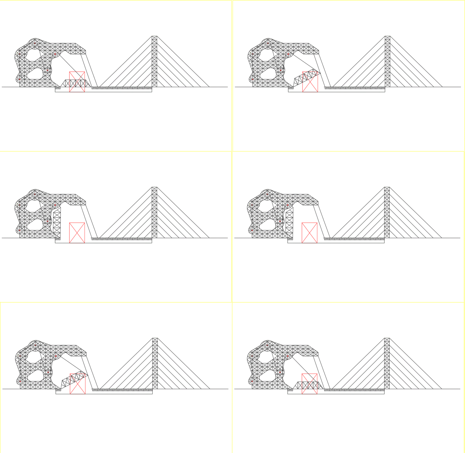
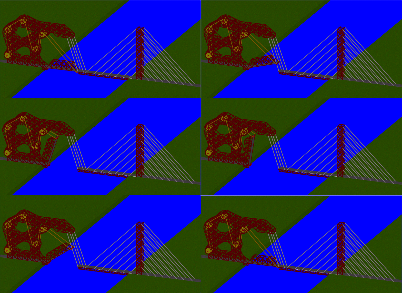
Hello there! This project is based around the concept that forms follows function. It required me to develop a functional pedestrian bridge with a span of 190 feet and an opening of 30 x 40 to allow boats to pass through. A prototype must be chosen for both the bridge and the opening mechanism. The opening mechanism that is incorporated into the bridge prototype is ultimately going to determine the form of the final bridge. Alterations to the form of the bridge can only be made if there is a functional need to do so, and not just to create a pattern or recognizable shape in the form. In my design I choose to combine a truss and cable-stayed bridge in order to have the most transformation that would ultimately follows the function. Cables and gears are incorporated to lift the roadway.
PROTOTYPES:
BRIDGES:
The 3 bridges that I used for design were, the Sydney Harbour Bridge (arched), the Burlington Bridge (truss), and the Arthur Ravenel Bridge (cable-stayed).

Sydney Harbour Bridge

ARCHED BRIDGE

Burlington Bridge

TRUSS BRIDGE

Arthur Ravenel Bridge

CABLE-STAYED BRIDGE
MOVEMENTS:
The 3 movements that i used to incorporate into my design were, a wine opener, a ratchet strap, and pliers. I broke down these movements and implemented these movements into my bridge design. The one movement that I ultimately chose was the ratchet strap because it uses a pulley system.
.jpg)
WINE OPENER
.jpg)

RATCHET STRAP


PLIERS
3x3 DIAGRAM
.jpg)
PRELIMINARY DESIGNS:
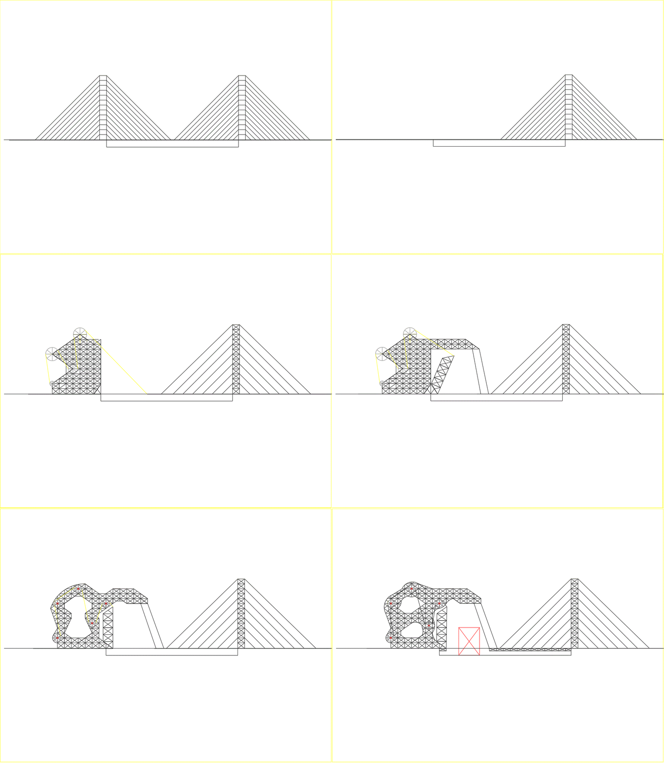
Out of the 3 x 3 diagram, I developed two preliminary design concepts. The first design uses a cable-stayed bridge with a pulley system. I transformed the tower on the left side of the bridge to fit the function. The left tower would tilt back using the pulley system in order for a 30 x 40 object to pass through. The second design uses an arched bridge with a pulley system. Once again the bridge is transformed to fit the function. A part of the roadway would tilt up to allow a 30 x 40 object to pass through. The preliminary design 1 is the idea that i chose to develop further into the final solution.

PRELIMINARY DESIGN 1

PRELIMINARY DESIGN 2
TRANSFORMATION

FINAL DESIGNS:
CLOSED


OPEN


MECHANISM
ANIMATION


